There are tons of different articles and books about guitar wiring and electric guitar electronics that make an attempt to explain what a guitar capacitor is and how it works. If you are anything like me, reading a manual is boring and I lose interest pretty quickly. Not to mention, most of these articles are pretty confusing and not easy to read.
That is why I decided to write this article. I want you to understand the important parts of capacitors and how to incorporate them in your guitar wiring setups. Guitar capacitors are actually pretty simply devices that can be explains pretty easily. In this article, I’ll talk about what a capacitor is, how it is measured, how it works, and how to choose one for your guitar.
What is a Guitar Capacitor?
Contents
Well, a guitar capacitor is no different than any other capacitor. It is just a lot smaller. A capacitor is simply a device that uses metal plates and a non-conducive substance or a dielectric to divert the flow of electricity or in a guitar’s case the flow of frequencies. A capacitor diverts the flow of lower frequencies and allows higher frequencies to pass through it. The cutoff point between the lower frequencies that are diverted and the higher frequencies that are allowed through depend on the value of the capacitor.
What are capacitor values?
A capacitor is measured in farads (F). A capacitor with a value of one farad is huge! Way too big for any guitar. Guitar capacitors are measured in fractions or decimals of a farad. Here are the three measurements you will probably hear:
- Microfarad (uF) = .000001 F
- Nanofarad (nF) = .000000001 F
- Picofarad (pF) = .000000000001 F
As you can see, 1 F or one farad would be a HUGE capacitor, as guitar capacitors are measured in millionths, billionths, and trillionths of one farad. Capacitors might use these measurements interchangeably. Here is a simple conversion for you.
- 55000pF = 55nF = .055uF
Generally Microfarads are used to measure caps down to about .01 uF and then the measurements switch to Picofarads to measure smaller capacitors.
How to read a capacitor
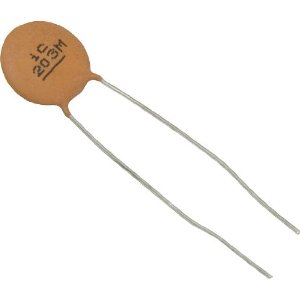
You may be looking at a capacitor and wondering what all the numbers on the back of it mean. Newer capacitors have a 3-digit code on the back to identify the value. Older capacitors, capacitors made before the 1970s, are generally not marked consistently. You may want to check these with a meter to find the true value. I know what you are thinking. Why don’t they just print the value instead of a code? Who knows? Luckily the code is easy to read.
The three-digit code can be translated into Picofarads pretty easily. The first two digits remain the same and the third digit refers to the number of zeros that need to be placed behind the first two. In other words, the code 222 represents 2200pF.
- 222 = 2200pF
- 223 = 22000pF
- 224 = 220000pF
Some capacitors also have a fourth letter in the code. This letter represents the tolerance percentage. Here is a list of the tolerance codes.
| Letter Code | Tolerance |
|---|---|
| B | — 0.1 pF |
| C | — 0.25 pF |
| D | — 0.5 pF |
| F | — 1% |
| G | — 2% |
| J | — 5% |
| K | — 10% |
| M | — 20% |
| Z | +80%, –20% |
A capacitor with the code 222F would be 2200pF +/- 22pF.
How do guitar capacitors affect guitar tone?
You may be thinking all this measurement stuff is great, but how does it work with my guitar? Remember I said that a capacitor’s job is to divert low frequencies and only allow the higher frequencies to pass through, right? Well, when you think about it that doesn’t make a whole lot of sense in a guitar. Most guitar players want to get rid of the high frequencies not pass them along.

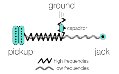
A cap is usually soldered in between the pickup and jack as a shortcut to the grounding wire. Since electricity will always follow the path of least resistance, the electricity will flow through the capacitor to the ground.
Now the capacitor starts to work. Only the high frequencies will be able to pass through the capacitor and escape through the ground. The lower frequencies will be trapped in the guitar circuit and will flow down to the jack and speaker. Thus the capacitor “rolls off” the high frequencies.

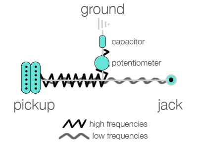
A capacitor in and of itself changes the tone of the guitar, but it is static. There is no way to alter the tone unless you put a resistor or guitar pot in the guitar circuit or wiring diagram. If you wire in a guitar pot before the capacitor, the pot will be able to control how much of the electricity flows through to the capacitor essentially changing the original cutoff point we talked about earlier. Generally a configuration like this where there is a cap and a pot are wired parallel with the signal is called an RC filter or low pass RC filter.
The pot acts like a dimmer on a light switch. When the pot is dialed to zero all the electricity flows through to the capacitor and your guitar will sound like you don’t have a pot wired in. If you dial the pot to ten, no electricity will flow to the capacitor and the guitar will sound like there isn’t a capacitor. Essentially the pot is used to adjust the amount of capacity the cap delivers.
What Capacitor should you use?
When you start looking at what capacitor to use in your guitar circuit, you have to think about what potentiometer you are going to use. Remember, the pot and the cap work together to produce your guitar’s tone. The most frequently used caps are the .047mF and .022mF. This is generally how these two caps are paired with pots:
- .047mF cap — 250k pot
- .022mF cap — 500k pot
As far as your actual guitar setup, it really depends what kind of sound you are looking for. With either of these pairings above, the tone can get kind of dark and muddy if the pot is turned all the way down. This is because the entire high end is being sent to ground due to the powerful capacitor. Many people with these setups rarely use the lower numbers on their dials because of this. That is why I suggest getting a slightly smaller capacitor. It will make your full range of pot more useful because the lower numbers, 0-3, will not filter so much high end.
As I said, great tone is a personal preference. It depends on the style of music you are playing the particular setup you are working with. This article should give you enough info to start messing around with what cap/pot combos work best for you.
Hope this helps explain a little more about how capacitors affect your guitar tone. Have fun testing out new setups!

Great info for a novice like myself, easy to understand many thanks
Excellent information. I’ve rewired a few guitars but never really knew which caps to use. Thanks for the more simple explanation. Very helpful.
Great up until the 0-3 comment. I didn’t quite get that. Is it 0.01 – 0.03?
Also, what would you say about a different cap for the bridge pickup?
I’m thinking 500k pots. A 0.001 (ceramic) treble bleed without a resistor on the volume pot, a 0.01 (Ceramic) on the middle/neck tone, and 0.0047 (paper and oil) on the bridge pickup tone.
At the moment, I never use the tone knobs because it’s too muddy and I have one 0.022 for both tone pots at the moment.
I’m modding a MIM strat, which won’t be very MIM for much longer. All new pots, pickups (dimarzio super distortion bridge, antiquities 2 seymour duncan middle, JB Jr seymour duncan neck), paint job, custom neck, different saddles, different tuning machines… only the trem will stay and I have it blocked.
If you have time to answer, I’m curious about your thoughts on this setup.
pot position 0 to 3
Super clear explanation! Wiring a HH guitar for coil splitting and trying to figure out the best cap options. Now understanding exactly how the caps work gives me some insight and my mind is exploding with ideas. Thanks for a great article!
I have read your article, I have zero knowledge when it comes to guitar wiring and I want to attempt changing my son’s Gibson LP. From my understanding, capacitor will only be installed on tone control knob (pot) not on the volume control knob (pot) am I right? Please answer.